บทความ

กำลังแสดงโพสต์จาก มีนาคม, 2019

สุ่มลูกเต๋า

รูปภาพ
หลักการทำงาน เมื่อกดสวิต arduimoจะสุ่มแดงledตั่งแต่1-6 Code int s1 = 10; int s2 = 9; int s3 = 8; int s4 = 7; int b = 11; int bs; long r; void setup () {   pinMode (s1, OUTPUT);   pinMode (s2, OUTPUT);   pinMode (s3, OUTPUT);   pinMode (s4, OUTPUT);   pinMode (b, INPUT);   randomSeed(analogRead(0)); } void loop() {   bs = digitalRead(b);     if (bs == LOW)   {     r = random(1, 7);     shuffle();     if (r == 1)     {       one();     }     if (r == 2)     {       two();     }     if (r == 3)     {       three();     }     if (r == 4)     {       four();     }     if (r == 5)     {  ...

RGB

รูปภาพ
หลักการทำงาน เมื่อ RGB รับค่าจากArduinoแล้ว ก็จะไปแสดงแบบผสมสี หากมีไฟเข้ามากกว่า1สี Code const int RED_PIN = 9; const int GREEN_PIN = 10; const int BLUE_PIN = 11; const int DISPLAY_TIME = 1000;  // used in mainColors() to determine the // length of time each color is displayed. void setup() //Configure the Arduino pins to be outputs to drive the LEDs {   pinMode(RED_PIN, OUTPUT);   pinMode(GREEN_PIN, OUTPUT);   pinMode(BLUE_PIN, OUTPUT); } void loop() {   mainColors();        // Red, Green, Blue, Yellow, Cyan, Purple, White   //  showSpectrum();    // Gradual fade from Red to Green to Blue to Red } /******************************************************************  * void mainColors()  * This function displays the eight "main" colors that the RGB LED  * can produce. If you'd like to use one of these colors in your  * own sketch, you can copy and paste that section ...

ไฟวิ่งled

รูปภาพ
หลักการทำงาน ให้arduinoอ่าน ปล้วไปแสดงผลที่ledโดยที่ CODE int timer = 100;           // ยิ่งจำนวนสูงเท่าใดเวลาก็จะยิ่งช้าลง void setup() {   // ใช้สำหรับวงเพื่อเริ่มต้นแต่ละพินเป็นเอาท์พุท:   for (int thisPin = 2; thisPin < 8; thisPin++) {     pinMode(thisPin, OUTPUT);   } } void loop() {   // วนรอบจากพินต่ำสุดไปสูงสุด:   for (int thisPin = 2; thisPin < 8; thisPin++) {     // turn the pin on:     digitalWrite(thisPin, HIGH);     delay(timer);     // turn the pin off:     digitalWrite(thisPin, LOW);   }   // วนรอบจากพินสูงสุดถึงต่ำสุด:   for (int thisPin = 7; thisPin >= 2; thisPin--) {     // turn the pin on:     digitalWrite(thisPin, HIGH);     delay(timer);     // turn the pin off:     digitalWrite(thisPin, LOW)...

วงจรนับ

รูปภาพ
วงจรนับ หลักการทำงาน เมื่อกดสวิทแล้ว arduinoก็จะ ไปประมวลผลแล้วไปแสดงผลที่LCD CODE #include <LiquidCrystal.h> LiquidCrystal lcd(12, 11, 5, 4, 3, 2); int data; int pin=8; int count = 10; void setup() {   // ใส่รหัสการตั้งค่าของคุณที่นี่เพื่อเรียกใช้ครั้งเดียว:   lcd.begin(16, 2);   pinMode(pin, INPUT); } void loop() {   // ใส่รหัสหลักที่นี่เพื่อเรียกใช้ซ้ำ ๆ :   data = digitalRead(pin);     lcd.setCursor(0, 0);     lcd.print("By AzeDocumenter");     lcd.setCursor(0, 1);     lcd.print("count");     if (data == HIGH){       lcd.setCursor(7,1);       lcd.print(count--);       delay(200);       lcd.clear();       if(count == 0)count=10;       } else {         lcd.setCursor(7, 1);   ...

ปุ่มหลายปุ่มบนขา1 Analog

รูปภาพ
หลักการทำงาน ขาanalogจะรับค่าไฟจากสวิท ่งสวิทนี้นจะมีค่าความต้านทานต่างกันจึงทำให้แยกแยะป่มุ ได้ CODE /* Multiple buttons on one Analog pin Example    Use 4 buttons to one bus to control 4 LEDs    Dev: Vasilakis Michalis // Date: 1/7/2015 // www.ardumotive.com */    //Constants const int yellowLed = 2; const int redLed    = 3; const int blueLed   = 4; const int greenLed  = 5; //Variables int buttonValue; //Stores analog value when button is pressed void setup() {   pinMode(yellowLed, OUTPUT);   pinMode(redLed, OUTPUT);   pinMode(blueLed, OUTPUT);   pinMode(greenLed, OUTPUT); } void loop() {   buttonValue = analogRead(A0); //Read analog value from A0 pin     //For 1st button:   if (buttonValue>=1010 && buttonValue<=1015){     digitalWrite(yellowLed, HIGH);   }   //For 2nd button:   else if (buttonValue>=...

ใช้volumeปรับความสว่าง

รูปภาพ
หลักการทำงาน เมื่อvolumeปรับค่าตัวresisterแล้วส่งไปยังarduino แล้วก็นำไปแสดงผลที่lde Code // ค่าคงที่เหล่านี้จะไม่เปลี่ยนแปลง พวกมันถูกใช้เพื่อตั้งชื่อให้กับพินที่ใช้: const int analogInPin = A0; const int analogOutPin = 9; int sensorValue = 0;        int outputValue = 0;      void setup() {   // เริ่มต้นการสื่อสารแบบอนุกรมที่ 9600 bps:   Serial.begin(9600); } void loop() {   // อ่านค่าอนาล็อก:   sensorValue = analogRead(analogInPin);   // แม็พกับช่วงของแอนะล็อก:   outputValue = map(sensorValue, 0, 1023, 0, 255);   // เปลี่ยนค่า analog out:   analogWrite(analogOutPin, outputValue);   // พิมพ์ผลลัพธ์ไปที่มอนิเตอร์อนุกรม:serial monitor:   Serial.print("sensor = ");   Serial.print(sensorValue);   Serial.print("\t output = ");   Serial.println(outputValue); // รอ 2 มิลลิวินาทีก่อนลูปถัดไปสำหรับตัวแปลงสัญญาณอนาล็อกเป็นดิจิตอลเพื่อชำระ หลังจากอ่านครั้งสุดท้...

Sound sensor

รูปภาพ
Sound sensor หลักการทำงาน เมื่อSound sensorได้รับเสียงจะส่งไปยังarduino แล้วแสดงที่led  code int soundsensor = A0; int led = 8; int val = 0; void setup() { pinMode(soundsensor,INPUT); pinMode(led,OUTPUT); } void loop() {   val = digitalRead(soundsensor);    อ่านค่าจากขาอินพุต   digitalWrite(led, val);     ตั้งค่าของหลอด LED ตามปุ่มกด }

Relay

รูปภาพ
Realy หลักการทำงาน arduinoส่งข้อมูลdataไปยังฺBC547 แล้วไปยังขดลวด แล้วสั่งให้LAMPทำงาน CODE int inpin = 2; void setup() { pinMode(inpin,OUTPUT); } void loop() {  digitalWrite(inpin,HIGH);  delay(1000); }

Servo Motor

รูปภาพ
Servo Motor หน้าที่ของ Servo Motor Servo Motor มีหน้าที่ขับเคลื่อนอุปกรณ์ของเครื่องจักรกลหรือระบบของการทํางานนั้นๆ ให้เป็นไปตามรูปแบบที่ ได้รับคําสั่งจากตัว Servo Driver พร้อมกับส่งสัญญาณป้อนกลับให้กับตัว Servo Driver ว่าตอนนี้ Servo Motor เคลื่อนที่ด้วย ความเร็วเท่าไหร่และระยะทางในการเคลื่อนที่เป็นระยะทางเท่าไหร่แล้ว ด้วยสัญญาณของตัว Encoder ที่อยู่ภายในตัว Servo Moter ทําให้การเคลื่อนที่ของ Servo Motor นั้นมีความแม่นยําสูง ด้วยองค์ประกอบข้างต้นทั้งหมดทั้งมวลนั้น พอจะทําให้ผู้ที่จะใช้งานหรือผู้ที่กําลังศึกษา พอที่จะมองภาพของการ ทํางานของระบบ Servo Motor ว่าองค์ประกอบของระบบหรือการที่จะใช้งาน Servo Motor นั้นต้องมีองค์ประกอบอะไรบ้างจึงจะใช้งาน Servo Motor ได้อย่างถูกต้องและมีประสิทธิภาพ หลักการทำงาน  arduinoส่งการทำงานไปยัง  Servo Motor code #include <Servo.h> Servo myservo;   void setup() {   myservo.attach(9); } void loop() {       myservo.write(0);       ...

motor drive simple

รูปภาพ
motor drive simple หลักการทำงาน arduinoส่งไปยังL293D แล้วก็ไปสั่งให้มอเตอร์ทำงาน Code const int motorPin1  = 5;   Pin 14 of L293 const int motorPin2  = 6;   Pin 10 of L293 const int motorPin3  = 10;  Pin  7 of L293 const int motorPin4  = 9;   Pin  2 of L293 This will run only one time. void setup(){     Set pins as outputs     pinMode(motorPin1, OUTPUT);     pinMode(motorPin2, OUTPUT);     pinMode(motorPin3, OUTPUT);     pinMode(motorPin4, OUTPUT);         Motor Control - Motor A motorPin1,motorpin2 & Motor B motorpin3,motorpin4     This code  will turn Motor A clockwise for 2 sec.     digitalWrite(motorPin1, HIGH);     digitalWrite(motorPin2, LOW);     digitalWrite(motorPin3, LOW);     digitalWrite(motorPi...

LCD

รูปภาพ
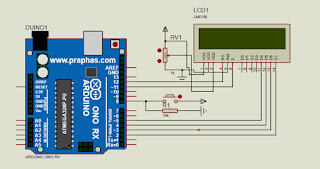
code #include <LiquidCrystal.h> const int rs = 12, en = 11, d4 = 5, d5 = 4, d6 = 3, d7 = 2; LiquidCrystal lcd(rs,en,d4,d5,d6,d7); void setup() {   // ตั้งค่าจำนวนคอลัมน์และแถวของ LCD:   lcd.begin(16, 2);   } void loop() {   // ตั้งค่าเคอร์เซอร์ไปที่คอลัมน์ 0, บรรทัด 1   //(หมายเหตุ: บรรทัด 1 คือแถวที่สองนับตั้งแต่การนับเริ่มต้นด้วย 0):   lcd.setCursor(0,0);   // ปริ้นคำที่จะให้lcdแสดงออกมา   lcd.print("hello!");     lcd.setCursor(0,1);   lcd.print("my name is yeen."); }

Gas Sensors

รูปภาพ
Gas Sensors  หลักการทำงาน? เมื่อจ่ายพลังงงานไฟฟ้าให้กับตัว sensor จะทำให้เกิดพลังงานความร้อนเพื่อให้สารเคมีในตัว sensor สามารถทำปฏิกิริยากับก๊าซแอลกอฮอล์ได้ แล้วก็ส่งไปยัง arduino แล้วนำไปปสดงผลที่led Code int flamesensor = A0; int led = 8; int val = 0; void setup() { pinMode(flamesensor,INPUT); pinMode(led,OUTPUT); } void loop() {   val = digitalRead(flamesensor);    digitalWrite(led, val);    }

flame sensor

รูปภาพ
flame sensor อุปกรณ์ตรวจจับเปลงเพลิง (flame detector) จะมีขนาดใหญ่และหนักกว่าอุปกรณ์ตรวจจับควัน (smoke detector) หรือ อุปกรณ์ตรวจจับความร้อน (heat detector) มีมุมองศาในการตรวจ (Field of View) เป็นรูปกรวยโคน โดยทั่วไปมีมุม 90 องศาขึ้นไป หลักการทำงาน เรียกว่าเป็น optical fire sensor ใช้การตรววจับแสงที่ ตอบสนองต่อความถี่ 1-15 Hz ซึ่งเป็นย่าน อินฟราเรด ที่มีความยาวคลื่น 1-2.8 ไมครอน ที่จะเกิดจากเปลวไฟเท่านั้น ซึ่งตามองไม่เห็นแสงนี้ ( ไม่ได้เกิดจาก แสงจากโคมไฟฉายหรือหลอดฟลูออเรสเซนต์ เพราะเป็นความถี่คนละย่านกัน) (เปลวไฟอาจให้ความยาวคลื่นถึง 4.3 ไมครอน แต่การตรวจจับที่ย่านถึง 2.8 ไมครอน ก็เพียงพอ เพราะต้องมีการออกแบบกรองสัญญาณ error จากแสงอาทิตย์ออกไปด้วย) ระยะในการตรวจจับ ไม่เกิน 50 ม. โดยทั่วไปก็มีรุ่น 25, 35, 45 ม. ความไวในการตรวจจับแปรตามระยะห่าง และ ขนาดเปลวไฟ ซึ่งการเลือกต้องเลือกระดับความไวให้ดี มี เช่น class 1, 2, 3 ซึ่งปกติแล้วโรงงานจะตั้งความไวไว้ที่ระดับสูง (High) หรือเป็น class 1 ถือเป็นอุปกรณ์อิเล็กทรอนิกส์ที่ต้องผ่านการทดสอบ EMC Immunity ตามมาตรฐาน IEC 50081-1, 50081-2, IEC ...

bluetooth hc 06

รูปภาพ
bluetooth hc 06 หลักการทำงาน  ส่งสัญญาญไปยัง bluetooth hc 06 เมื่อ bluetooth hc 06 ได้รับสัญญาญแล้วก็จะส่งไปยังarduino แล้วแสดงผลไปยังled Code #define d1 8 #define d2 9 #define d3 10 #define d4 11 void setup() {   pinMode(d1, OUTPUT);   pinMode(d2, OUTPUT);   pinMode(d3, OUTPUT);   pinMode(d4, OUTPUT);   Serial.begin(9600); } void loop() {   while(Serial.available())   {     char In=Serial.read();         if(In=='a' || In=='A')          {       digitalWrite(d1, HIGH);       digitalWrite(d2, LOW);       digitalWrite(d3, LOW);       digitalWrite(d4, LOW);     }          else if(In=='s' || In=='S')                {   ...

Mini Project

รูปภาพ
Mini Project เรื่อง เครื่องตรวจจับแสงLDR รูป วงจร เครื่องตรวจจับแสงLDR รูปโค้ด Auduino โค้ต #include <LiquidCrystal.h> int ledPin = 13; int buzzerPin = 12; int ldrPin = A0; LiquidCrystal lcd(11, 10, 5, 4, 3, 2); void setup () {   Serial.begin(9600);   pinMode(ledPin, OUTPUT);   pinMode(buzzerPin, OUTPUT);   pinMode(ldrPin, INPUT);   lcd.begin(16, 2);   lcd.clear(); } void loop() {  int ldrStatus = analogRead(ldrPin);   if (ldrStatus >=50){     tone(buzzerPin,100);     digitalWrite(ledPin, HIGH);     delay(100);     noTone(buzzerPin);     digitalWrite(ledPin, LOW);     delay(100);     Serial.println("----------- ALARM ACTIVATED -----------");     lcd.setCursor(0, 0);     lcd.print("-----ALARM-----");     lcd.setCursor(0, 1);     lcd.print("---AC...