บทความ

สุ่มลูกเต๋า

รูปภาพ
หลักการทำงาน เมื่อกดสวิต arduimoจะสุ่มแดงledตั่งแต่1-6 Code int s1 = 10; int s2 = 9; int s3 = 8; int s4 = 7; int b = 11; int bs; long r; void setup () {   pinMode (s1, OUTPUT);   pinMode (s2, OUTPUT);   pinMode (s3, OUTPUT);   pinMode (s4, OUTPUT);   pinMode (b, INPUT);   randomSeed(analogRead(0)); } void loop() {   bs = digitalRead(b);     if (bs == LOW)   {     r = random(1, 7);     shuffle();     if (r == 1)     {       one();     }     if (r == 2)     {       two();     }     if (r == 3)     {       three();     }     if (r == 4)     {       four();     }     if (r == 5)     {  ...

RGB

รูปภาพ
หลักการทำงาน เมื่อ RGB รับค่าจากArduinoแล้ว ก็จะไปแสดงแบบผสมสี หากมีไฟเข้ามากกว่า1สี Code const int RED_PIN = 9; const int GREEN_PIN = 10; const int BLUE_PIN = 11; const int DISPLAY_TIME = 1000;  // used in mainColors() to determine the // length of time each color is displayed. void setup() //Configure the Arduino pins to be outputs to drive the LEDs {   pinMode(RED_PIN, OUTPUT);   pinMode(GREEN_PIN, OUTPUT);   pinMode(BLUE_PIN, OUTPUT); } void loop() {   mainColors();        // Red, Green, Blue, Yellow, Cyan, Purple, White   //  showSpectrum();    // Gradual fade from Red to Green to Blue to Red } /******************************************************************  * void mainColors()  * This function displays the eight "main" colors that the RGB LED  * can produce. If you'd like to use one of these colors in your  * own sketch, you can copy and paste that section ...

ไฟวิ่งled

รูปภาพ
หลักการทำงาน ให้arduinoอ่าน ปล้วไปแสดงผลที่ledโดยที่ CODE int timer = 100;           // ยิ่งจำนวนสูงเท่าใดเวลาก็จะยิ่งช้าลง void setup() {   // ใช้สำหรับวงเพื่อเริ่มต้นแต่ละพินเป็นเอาท์พุท:   for (int thisPin = 2; thisPin < 8; thisPin++) {     pinMode(thisPin, OUTPUT);   } } void loop() {   // วนรอบจากพินต่ำสุดไปสูงสุด:   for (int thisPin = 2; thisPin < 8; thisPin++) {     // turn the pin on:     digitalWrite(thisPin, HIGH);     delay(timer);     // turn the pin off:     digitalWrite(thisPin, LOW);   }   // วนรอบจากพินสูงสุดถึงต่ำสุด:   for (int thisPin = 7; thisPin >= 2; thisPin--) {     // turn the pin on:     digitalWrite(thisPin, HIGH);     delay(timer);     // turn the pin off:     digitalWrite(thisPin, LOW)...

วงจรนับ

รูปภาพ
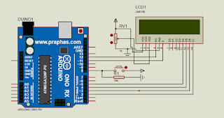
วงจรนับ หลักการทำงาน เมื่อกดสวิทแล้ว arduinoก็จะ ไปประมวลผลแล้วไปแสดงผลที่LCD CODE #include <LiquidCrystal.h> LiquidCrystal lcd(12, 11, 5, 4, 3, 2); int data; int pin=8; int count = 10; void setup() {   // ใส่รหัสการตั้งค่าของคุณที่นี่เพื่อเรียกใช้ครั้งเดียว:   lcd.begin(16, 2);   pinMode(pin, INPUT); } void loop() {   // ใส่รหัสหลักที่นี่เพื่อเรียกใช้ซ้ำ ๆ :   data = digitalRead(pin);     lcd.setCursor(0, 0);     lcd.print("By AzeDocumenter");     lcd.setCursor(0, 1);     lcd.print("count");     if (data == HIGH){       lcd.setCursor(7,1);       lcd.print(count--);       delay(200);       lcd.clear();       if(count == 0)count=10;       } else {         lcd.setCursor(7, 1);   ...

ปุ่มหลายปุ่มบนขา1 Analog

รูปภาพ
หลักการทำงาน ขาanalogจะรับค่าไฟจากสวิท ่งสวิทนี้นจะมีค่าความต้านทานต่างกันจึงทำให้แยกแยะป่มุ ได้ CODE /* Multiple buttons on one Analog pin Example    Use 4 buttons to one bus to control 4 LEDs    Dev: Vasilakis Michalis // Date: 1/7/2015 // www.ardumotive.com */    //Constants const int yellowLed = 2; const int redLed    = 3; const int blueLed   = 4; const int greenLed  = 5; //Variables int buttonValue; //Stores analog value when button is pressed void setup() {   pinMode(yellowLed, OUTPUT);   pinMode(redLed, OUTPUT);   pinMode(blueLed, OUTPUT);   pinMode(greenLed, OUTPUT); } void loop() {   buttonValue = analogRead(A0); //Read analog value from A0 pin     //For 1st button:   if (buttonValue>=1010 && buttonValue<=1015){     digitalWrite(yellowLed, HIGH);   }   //For 2nd button:   else if (buttonValue>=...

ใช้volumeปรับความสว่าง

รูปภาพ
หลักการทำงาน เมื่อvolumeปรับค่าตัวresisterแล้วส่งไปยังarduino แล้วก็นำไปแสดงผลที่lde Code // ค่าคงที่เหล่านี้จะไม่เปลี่ยนแปลง พวกมันถูกใช้เพื่อตั้งชื่อให้กับพินที่ใช้: const int analogInPin = A0; const int analogOutPin = 9; int sensorValue = 0;        int outputValue = 0;      void setup() {   // เริ่มต้นการสื่อสารแบบอนุกรมที่ 9600 bps:   Serial.begin(9600); } void loop() {   // อ่านค่าอนาล็อก:   sensorValue = analogRead(analogInPin);   // แม็พกับช่วงของแอนะล็อก:   outputValue = map(sensorValue, 0, 1023, 0, 255);   // เปลี่ยนค่า analog out:   analogWrite(analogOutPin, outputValue);   // พิมพ์ผลลัพธ์ไปที่มอนิเตอร์อนุกรม:serial monitor:   Serial.print("sensor = ");   Serial.print(sensorValue);   Serial.print("\t output = ");   Serial.println(outputValue); // รอ 2 มิลลิวินาทีก่อนลูปถัดไปสำหรับตัวแปลงสัญญาณอนาล็อกเป็นดิจิตอลเพื่อชำระ หลังจากอ่านครั้งสุดท้...

Sound sensor

รูปภาพ
Sound sensor หลักการทำงาน เมื่อSound sensorได้รับเสียงจะส่งไปยังarduino แล้วแสดงที่led  code int soundsensor = A0; int led = 8; int val = 0; void setup() { pinMode(soundsensor,INPUT); pinMode(led,OUTPUT); } void loop() {   val = digitalRead(soundsensor);    อ่านค่าจากขาอินพุต   digitalWrite(led, val);     ตั้งค่าของหลอด LED ตามปุ่มกด }